Product Description
RV series Characteristics
- RV – Sizes:–150
- Input Options: with input shaft, With Square flange,With Input Flange
- Input Power 0.06 to 11 kW
- RV-Size from 030 to 105 in die-cast aluminium alloy budy and over 110 in cast iron
- Ratios between 5 and 100
- Max torque 1550 N.m and admissible output radial loads max 8771 N
- Aluminium units are supplied complete with synthetic oil and allow for universal mounting positions, with no need to modify lubricant quantity
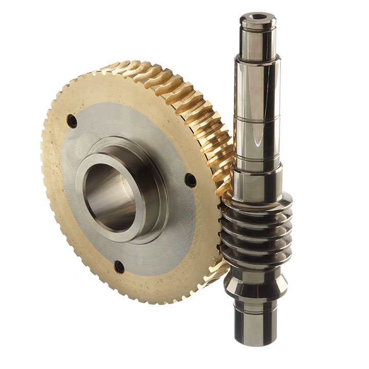
- Worm wheel: Copper (KK Cu).
- Loading capacity in accordance with: ISO 9001:2015/GB/T 19001-2016
- Size 030 and over are painted with RAL 5571 blue
- Worm gear reducers are available with diffferent combinations: NMRV+NMRV, NMRVpower+NMRV, JWB+NMRV
- NMRV, NRV+VS,NMRV+AS,NMRV+VS,NMRV+F
- Options: torque arm, output flange, viton oil seals, low/high temperature oil, filling/drain/breather/level plug.
Basic models can be applied to a wide range of power reduction ratios from 5 to 1000.
Warranty: One year from date of delivery.
DATASHEET
| Type | Old Type | Output Torque | Output Shaft Dia. |
| SNW030 | RV030 | 21N.m | φ14 |
| SNW040 | RV040 | 45N.m | φ19 |
| SNW050 | RV050 | 84N.m | φ25 |
| SNW063 | RV063 | 160N.m | φ25 |
| SNW075 | RV075 | 230N.m | φ28 |
| SNW090 | RV090 | 410N.m | φ35 |
| SNW105 | RV105 | 630N.m | φ42 |
| SNW110 | RV110 | 725N.m | φ42 |
| SNW130 | RV130 | 1050N.m | φ45 |
| SNW150 | RV150 | 1550N.m | φ50 |
About CHINAMFG Drive
ZheJiang CHINAMFG Drive Co.,Ltd(Starshine) have a strong technical force with over 350 employees at present, including over 30 engineering technicians, 30 quality inspectors, covering an area of 80000 square CHINAMFG and kinds of advanced processing machines and testing equipments. We have a good foundation for the industry application development and service of high-end speed reducers & variators owning to the provincial engineering technology research center,the lab of gear speed reducers, and the base of modern R&D.
Our products are widely used in ceramic industry, glass industry, woodworking machinery , high voltage switch, food & beverage, packaging & printing, Storage & logistics, hoisting & transportation facilities…etc , and CHINAMFG technically provide the professional product & service for the medium and high-end customers, and our gearboxes are best-selling in domestic, and even in abroad , such as in Europe, North America, South America, Middle East, South Asia, Southeast Asia, Africa…etc.
In the future , CHINAMFG will hold the creed of “serving customer, diligence & simplicity, self-criticism, innovation, honesty, teamwork”, and the concept of “quality creates value” to focus on the customers’ requirements and provide them the competitive transmission solution and create value for them constantly, and make a high-end equipment manufacturing industry and create a preferred brand of replacing import products and upgrading continuously for the end users.
Team
Quality Control
Quality:Insist on Improvement,Strive for CHINAMFG With the development of equipment manufacturing indurstry,customer never satirsfy with the current quality of our products,on the contrary,wcreate the value of quality.
Quality policy:to enhance the overall level in the field of power transmission
Quality View:Continuous Improvement , pursuit of CHINAMFG
Quality Philosophy:Quality creates value
3. Incoming Quality Control
To establish the AQL acceptable level of incoming material control, to provide the material for the whole inspection, sampling, immunity. On the acceptance of qualified products to warehousing, substandard goods to take return, check, rework, rework inspection; responsible for tracking bad, to monitor the supplier to take corrective measures to prevent recurrence.
4. Process Quality Control
The manufacturing site of the first examination, inspection and final inspection, sampling according to the requirements of some projects, judging the quality change trend; found abnormal phenomenon of manufacturing, and supervise the production department to improve, eliminate the abnormal phenomenon or state
5. FQC(Final QC)
After the manufacturing department will complete the product, stand in the customer’s position on the finished product quality verification, in order to ensure the quality of customer expectations and needs.
6. OQC(Outgoing QC)
After the product sample inspection to determine the qualified, allowing storage, but when the finished product from the warehouse before the formal delivery of the goods, there is a check, this is called the shipment inspection.Check content:In the warehouse storage and transfer status to confirm, while confirming the delivery of the product is a product inspection to determine the qualified products.
Packing
Delivery
/* March 10, 2571 17:59:20 */!function(){function s(e,r){var a,o={};try{e&&e.split(“,”).forEach(function(e,t){e&&(a=e.match(/(.*?):(.*)$/))&&1
| Application: | Motor, Machinery, Marine, Agricultural Machinery |
|---|---|
| Function: | Distribution Power, Change Drive Torque, Change Drive Direction, Speed Changing, Speed Reduction |
| Layout: | Right Angle |
| Hardness: | Hardened Tooth Surface |
| Installation: | Vertical or Horizontal |
| Step: | Single or Double Stages |
| Customization: |
Available
| Customized Request |
|---|

How does a worm gear impact the overall efficiency of a system?
A worm gear has a significant impact on the overall efficiency of a system due to its unique design and mechanical characteristics. Here’s a detailed explanation of how a worm gear affects system efficiency:
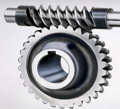
A worm gear consists of a worm (a screw-like gear) and a worm wheel (a cylindrical gear with teeth). When the worm rotates, it engages with the teeth of the worm wheel, causing the wheel to rotate. The main factors influencing the efficiency of a worm gear system are:
- Gear Reduction Ratio: Worm gears are known for their high gear reduction ratios, which are the ratio of the number of teeth on the worm wheel to the number of threads on the worm. This high reduction ratio allows for significant speed reduction and torque multiplication. However, the larger the reduction ratio, the more frictional losses occur, resulting in lower efficiency.
- Mechanical Efficiency: The mechanical efficiency of a worm gear system refers to the ratio of the output power to the input power, accounting for losses due to friction and inefficiencies in power transmission. Worm gears typically have lower mechanical efficiency compared to other gear types, primarily due to the sliding action between the worm and the worm wheel teeth. This sliding contact generates higher frictional losses, resulting in reduced efficiency.
- Self-Locking: One advantageous characteristic of worm gears is their self-locking property. Due to the angle of the worm thread, the worm gear system can prevent the reverse rotation of the output shaft without the need for additional braking mechanisms. While self-locking is beneficial for maintaining position and preventing backdriving, it also increases the frictional losses and reduces the efficiency when the gear system needs to be driven in the opposite direction.
- Lubrication: Proper lubrication is crucial for minimizing friction and maintaining efficient operation of a worm gear system. Inadequate or improper lubrication can lead to increased friction and wear, resulting in lower efficiency. Regular lubrication maintenance, including monitoring viscosity, cleanliness, and lubricant condition, is essential for optimizing efficiency and reducing power losses.
- Design and Manufacturing Quality: The design and manufacturing quality of the worm gear components play a significant role in determining the system’s efficiency. Precise machining, accurate tooth profiles, proper gear meshing, and appropriate surface finishes contribute to reducing friction and enhancing efficiency. High-quality materials with suitable hardness and smoothness also impact the overall efficiency of the system.
- Operating Conditions: The operating conditions, such as the load applied, rotational speed, and temperature, can affect the efficiency of a worm gear system. Higher loads, faster speeds, and extreme temperatures can increase frictional losses and reduce overall efficiency. Proper selection of the worm gear system based on the expected operating conditions is critical for optimizing efficiency.
It’s important to note that while worm gears may have lower mechanical efficiency compared to some other gear types, they offer unique advantages such as high gear reduction ratios, compact design, and self-locking capabilities. The suitability of a worm gear system depends on the specific application requirements and the trade-offs between efficiency, torque transmission, and other factors.
When designing or selecting a worm gear system, it is essential to consider the desired balance between efficiency, torque requirements, positional stability, and other performance factors to ensure optimal overall system efficiency.

How do you ensure proper alignment when connecting a worm gear?
Ensuring proper alignment when connecting a worm gear is crucial for the smooth and efficient operation of the gear system. Here’s a detailed explanation of the steps involved in achieving proper alignment:
- Pre-alignment preparation: Before connecting the worm gear, it is essential to prepare the components for alignment. This includes cleaning the mating surfaces of the gear and shaft, removing any debris or contaminants, and inspecting for any signs of damage or wear that could affect the alignment process.
- Measurement and analysis: Accurate measurement and analysis of the gear and shaft alignment are essential for achieving proper alignment. This typically involves using precision alignment tools such as dial indicators, laser alignment systems, or optical alignment instruments. These tools help measure the relative positions and angles of the gear and shaft and identify any misalignment.
- Adjustment of mounting surfaces: Based on the measurement results, adjustments may be required to align the mounting surfaces of the gear and shaft. This can involve shimming or machining the mounting surfaces to achieve the desired alignment. Care should be taken to ensure that the adjustments are made evenly and symmetrically to maintain the integrity of the gear system.
- Alignment correction: Once the mounting surfaces are prepared, the gear and shaft can be connected. During this process, it is important to carefully align the gear and shaft to minimize misalignment. This can be done by observing the alignment readings and making incremental adjustments as necessary. The specific adjustment method may vary depending on the type of coupling used to connect the gear and shaft (e.g., keyway, spline, or flange coupling).
- Verification and final adjustment: After connecting the gear and shaft, it is crucial to verify the alignment once again. This involves re-measuring the alignment using the alignment tools to ensure that the desired alignment specifications have been achieved. If any deviations are detected, final adjustments can be made to fine-tune the alignment until the desired readings are obtained.
- Secure fastening: Once the proper alignment is achieved, the gear and shaft should be securely fastened using appropriate fasteners and tightening procedures. It is important to follow the manufacturer’s recommendations for torque values and tightening sequences to ensure proper clamping force and prevent any loosening or slippage.
It is worth noting that the alignment process may vary depending on the specific gear system, coupling type, and alignment tools available. Additionally, it is important to refer to the manufacturer’s guidelines and specifications for the particular gear and coupling being used, as they may provide specific instructions or requirements for alignment.
Proper alignment should not be considered a one-time task but an ongoing maintenance practice. Regular inspections and realignment checks should be performed periodically or whenever there are indications of misalignment, such as abnormal noise, vibration, or accelerated wear. By ensuring proper alignment during the initial connection and maintaining it throughout the gear’s operational life, the gear system can operate optimally, minimize wear, and extend its service life.

How do you calculate the gear ratio of a worm gear?
Calculating the gear ratio of a worm gear involves determining the number of teeth on the worm wheel and the pitch diameter of both the worm and worm wheel. Here’s the step-by-step process:
- Determine the number of teeth on the worm wheel (Zworm wheel). This information can usually be obtained from the gear specifications or by physically counting the teeth.
- Measure or determine the pitch diameter of the worm (Dworm) and the worm wheel (Dworm wheel). The pitch diameter is the diameter of the reference circle that corresponds to the pitch of the gear. It can be measured directly or calculated using the formula: Dpitch = (Z / P), where Z is the number of teeth and P is the circular pitch (the distance between corresponding points on adjacent teeth).
- Calculate the gear ratio (GR) using the following formula: GR = (Zworm wheel / Zworm) * (Dworm wheel / Dworm).
The gear ratio represents the speed reduction and torque multiplication provided by the worm gear system. A higher gear ratio indicates a greater reduction in speed and higher torque output, while a lower gear ratio results in less speed reduction and lower torque output.
It’s worth noting that in worm gear systems, the gear ratio is also influenced by the helix angle and lead angle of the worm. These angles determine the rate of rotation and axial movement per revolution of the worm. Therefore, when selecting a worm gear, it’s important to consider not only the gear ratio but also the specific design parameters and performance characteristics of the worm and worm wheel.


editor by CX 2023-12-29