Product Description
Product Description
A rack is a special gear whose teeth are distributed on a bar.
The rack is also divided into straight rack and helical rack, which are paired with straight cylindrical gear and helical cylindrical gear respectively; The tooth profile of a rack is a straight line rather than an involute (plane for the tooth surface), which is equivalent to a cylindrical gear with an infinitely large dividing circle radius.
Detailed Photos
Product Parameters
Our Advantages
Packaging & Shipping
WHY CHOOSE US
Comprehensive Product Portfolio We produce and supply a wide range of power transmission
products including drive chains, leaf chains, conveyor chains, agricultural chains, sprockets, and
couplings. This one-store-for-all shopping experience will significantly reduce your searching costs while
guarantee youfind what you want at 1 click.
Value Choice Products Our products are the best combination of quality and price, and you get what
you want within your budgets
Seasoned Sales Associates and Engineers We have 15 seasoned sales associates and 5 engineers;
on our team at your disposal any time when you need a helping hand. They are well trained with industry
know-now and will always respond to your requests within 24 hours.
100% Customer Retention Rate Our regular customers from overseas come back not just for our
premium quality products, but for the superior services that we’ve provided over the years
FAQ
Q1: What’s your average lead time?
A: It varies. Our regular end-to-end lead time is 1-2 months.. We also provide express shipments for rush orders. For details,please consult our sales associate.
Q2: Is your price better than your competitors given the same quality?
A: Definitely YES. We provide the most competitive price in the power transmission industry. If price disparity exists, we’ll be more than happy to do a price match.
Q3: Can you make chains according to my CAD drawings?
A: Yes. Besides the regular standard chains, we produce non-standard and custom-design products to meet the specific technical requirements. In reality, a sizable portion of our production capacity is assigned to make non-standard products.
Q4: Can we inspect the goods before shipment?
A: Yes. You or your representative or any third-party inspection party assigned is allowed access to our facility and do the inspection.
Q5: What kind of payment method is acceptable for your mill?
A: We’re flexible. We take T/T, L/C, or any other online payment methods so long as it’s applicable for you.
Q6: What if I have any other questions?
A: Whenever in doubt, you’re always encouraged to consult our sales associate any time – They will help you to your satisfaction.
/* January 22, 2571 19:08:37 */!function(){function s(e,r){var a,o={};try{e&&e.split(“,”).forEach(function(e,t){e&&(a=e.match(/(.*?):(.*)$/))&&1
| Application: | Motor, Machinery |
|---|---|
| Hardness: | Hardened Tooth Surface |
| Gear Position: | External Gear |
| Customization: |
Available
| Customized Request |
|---|
.shipping-cost-tm .tm-status-off{background: none;padding:0;color: #1470cc}
|
Shipping Cost:
Estimated freight per unit. |
about shipping cost and estimated delivery time. |
|---|
| Payment Method: |
|
|---|---|
|
Initial Payment Full Payment |
| Currency: | US$ |
|---|
| Return&refunds: | You can apply for a refund up to 30 days after receipt of the products. |
|---|

How does a worm gear impact the overall efficiency of a system?
A worm gear has a significant impact on the overall efficiency of a system due to its unique design and mechanical characteristics. Here’s a detailed explanation of how a worm gear affects system efficiency:
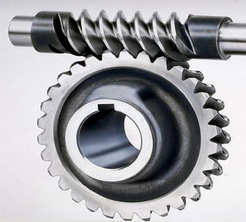
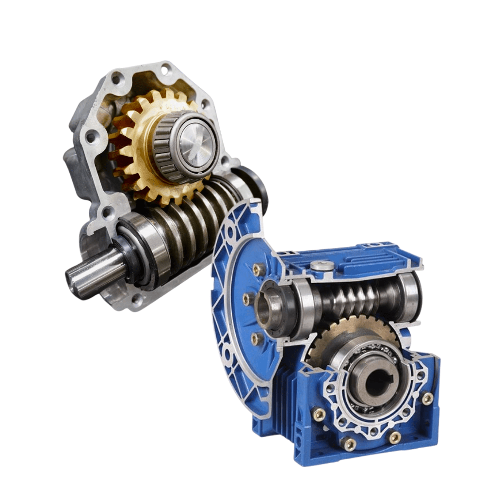
A worm gear consists of a worm (a screw-like gear) and a worm wheel (a cylindrical gear with teeth). When the worm rotates, it engages with the teeth of the worm wheel, causing the wheel to rotate. The main factors influencing the efficiency of a worm gear system are:
- Gear Reduction Ratio: Worm gears are known for their high gear reduction ratios, which are the ratio of the number of teeth on the worm wheel to the number of threads on the worm. This high reduction ratio allows for significant speed reduction and torque multiplication. However, the larger the reduction ratio, the more frictional losses occur, resulting in lower efficiency.
- Mechanical Efficiency: The mechanical efficiency of a worm gear system refers to the ratio of the output power to the input power, accounting for losses due to friction and inefficiencies in power transmission. Worm gears typically have lower mechanical efficiency compared to other gear types, primarily due to the sliding action between the worm and the worm wheel teeth. This sliding contact generates higher frictional losses, resulting in reduced efficiency.
- Self-Locking: One advantageous characteristic of worm gears is their self-locking property. Due to the angle of the worm thread, the worm gear system can prevent the reverse rotation of the output shaft without the need for additional braking mechanisms. While self-locking is beneficial for maintaining position and preventing backdriving, it also increases the frictional losses and reduces the efficiency when the gear system needs to be driven in the opposite direction.
- Lubrication: Proper lubrication is crucial for minimizing friction and maintaining efficient operation of a worm gear system. Inadequate or improper lubrication can lead to increased friction and wear, resulting in lower efficiency. Regular lubrication maintenance, including monitoring viscosity, cleanliness, and lubricant condition, is essential for optimizing efficiency and reducing power losses.
- Design and Manufacturing Quality: The design and manufacturing quality of the worm gear components play a significant role in determining the system’s efficiency. Precise machining, accurate tooth profiles, proper gear meshing, and appropriate surface finishes contribute to reducing friction and enhancing efficiency. High-quality materials with suitable hardness and smoothness also impact the overall efficiency of the system.
- Operating Conditions: The operating conditions, such as the load applied, rotational speed, and temperature, can affect the efficiency of a worm gear system. Higher loads, faster speeds, and extreme temperatures can increase frictional losses and reduce overall efficiency. Proper selection of the worm gear system based on the expected operating conditions is critical for optimizing efficiency.
It’s important to note that while worm gears may have lower mechanical efficiency compared to some other gear types, they offer unique advantages such as high gear reduction ratios, compact design, and self-locking capabilities. The suitability of a worm gear system depends on the specific application requirements and the trade-offs between efficiency, torque transmission, and other factors.
When designing or selecting a worm gear system, it is essential to consider the desired balance between efficiency, torque requirements, positional stability, and other performance factors to ensure optimal overall system efficiency.

What are the potential challenges in designing and manufacturing worm gears?
Designing and manufacturing worm gears can present several challenges due to their unique characteristics and operating conditions. Here’s a detailed explanation of the potential challenges involved:
- Complex geometry: Worm gears have complex geometry with helical threads on the worm shaft and corresponding teeth on the worm wheel. Designing the precise geometry of the gear teeth, including the helix angle, lead angle, and tooth profile, requires careful analysis and calculation to ensure proper meshing and efficient power transmission.
- Gear materials and heat treatment: Selecting suitable materials for worm gears is critical to ensure strength, wear resistance, and durability. The materials must have good friction and wear properties, as well as the ability to withstand the sliding and rolling contact between the worm and the worm wheel. Additionally, heat treatment processes such as carburizing or induction hardening may be necessary to enhance the gear’s surface hardness and improve its load-carrying capacity.
- Lubrication and cooling: Worm gears operate under high contact pressures and sliding velocities, resulting in significant heat generation and lubrication challenges. Proper lubrication is crucial to reduce friction, wear, and heat buildup. Ensuring effective lubricant distribution to all contact surfaces, managing lubricant temperature, and providing adequate cooling mechanisms are important considerations in worm gear design and manufacturing.
- Backlash control: Controlling backlash, which is the clearance between the worm and the worm wheel, is crucial for precise motion control and positional accuracy. Designing the gear teeth and adjusting the clearances to minimize backlash while maintaining proper tooth engagement is a challenge that requires careful consideration of factors such as gear geometry, tolerances, and manufacturing processes.
- Manufacturing accuracy: Achieving the required manufacturing accuracy in worm gears can be challenging due to their complex geometry and tight tolerances. The accurate machining of gear teeth, maintaining proper tooth profiles, and achieving the desired surface finish require advanced machining techniques, specialized tools, and skilled operators.
- Noise and vibration: Worm gears can generate noise and vibration due to the sliding contact between the gear teeth. Designing the gear geometry, tooth profiles, and surface finishes to minimize noise and vibration is a challenge. Additionally, the selection of appropriate materials, lubrication methods, and gear housing design can help reduce noise and vibration levels.
- Efficiency and power loss: Worm gears inherently have lower efficiency compared to other types of gear systems due to the sliding contact and high gear ratios. Minimizing power loss and improving efficiency through optimized gear design, material selection, lubrication, and manufacturing accuracy is a challenge that requires careful balancing of various factors.
- Wear and fatigue: Worm gears are subjected to high contact stresses and cyclic loading, which can lead to wear, pitting, and fatigue failure. Designing the gear teeth for proper load distribution, selecting appropriate materials, and applying suitable surface treatments or coatings are essential to mitigate wear and fatigue issues.
- Cost considerations: Designing and manufacturing worm gears can be cost-intensive due to the complexity of the gear geometry, material requirements, and precision manufacturing processes. Balancing performance requirements with cost considerations is a challenge that requires careful evaluation of the gear’s intended application, performance expectations, and budget constraints.
Addressing these challenges requires a comprehensive understanding of gear design principles, manufacturing processes, material science, and lubrication technologies. Collaboration between design engineers, manufacturing experts, and material specialists is often necessary to overcome these challenges and ensure the successful design and production of high-quality worm gears.

Can you explain the concept of worm and worm wheel in a worm gear?
In a worm gear system, the worm and worm wheel are the two primary components that work together to transmit motion and power. Here’s an explanation of the concept:
Worm:
The worm is a cylindrical shaft with a helical thread wrapped around it. It resembles a screw with a spiral groove. The helical thread is called the worm’s thread or worm thread. The worm is the driving component in the worm gear system.
When the worm rotates, the helical thread engages with the teeth of the worm wheel, causing the worm wheel to rotate. The angle of the helical thread creates a wedging action against the teeth of the worm wheel, resulting in a high gear reduction ratio.
One important characteristic of the worm is its self-locking nature. Due to the angle of the helical thread, the worm can drive the worm wheel, but the reverse is not true. The self-locking feature prevents the worm wheel from backdriving the worm, providing a mechanical brake or holding position in the system.
The worm can be made from various materials such as steel, bronze, or even plastics, depending on the application requirements. It is often mounted on a shaft and supported by bearings for smooth rotation.
Worm Wheel:
The worm wheel, also known as the worm gear, is the driven component in the worm gear system. It is a gear with teeth that mesh with the helical thread of the worm. The teeth on the worm wheel are typically helical and cut to match the angle and pitch of the worm’s thread.
As the worm rotates, its helical thread engages with the teeth of the worm wheel, causing the worm wheel to rotate. The rotation of the worm wheel is in the same direction as the worm’s rotation, but the speed is significantly reduced due to the high gear reduction ratio of the worm gear system.
The worm wheel is usually larger in diameter compared to the worm, allowing for a higher gear reduction ratio. It can be made from materials such as steel, bronze, or cast iron, depending on the application’s torque and durability requirements.
Together, the worm and worm wheel form a compact and efficient gear system that provides high gear reduction and self-locking capabilities. They are commonly used in various applications where precise motion control, high torque, and compactness are required, such as elevators, steering systems, and machine tools.


editor by CX 2024-03-30